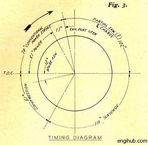
This graphical diagram is known as the valve timing diagram in automobile engineering.
In the petrol engine, various strokes are performed to obtain the results from an engine.
By denoting the corresponding position of the piston attached to the crankshaft at which these strokes occur, you can draw the exact moment in the sequence of events at which the valves are open and close.
The valve timing diagram is modified to set better charging and exhausting performance as there is always a difference between theory and practice.
The valve timing diagram is drawn for two complete revolutions of the crankshaft means for one complete cycle.
Following strokes are performed in a four-stroke petrol engine
(Based on the below strokes, you can draw a Valve Timing Diagram for an Engine)
Suction Stroke
The piston starts moving from the top dead center resulting opening of the inlet valve.
The fresh charge of the air-fuel mixture enters a cylinder.
The piston moves further to the bottom dead center
Compression Stroke
Inlet and exhaust valves are in the closed position.
And the piston starts moving upward from the bottom dead center to the top dead center.
Hence compression of charge took place.
Expansion Stroke
The ignition is started by a spark plug just before the end of the compression stroke.
Both inlet and exhaust valves are still closed.
A rapid explosion takes place which is followed by the expansion of hot gases pushing the piston to its bottom dead center.
In this stroke, the useful work is obtained from the engine which is why it is also called a working stroke.
Exhaust Stroke
The piston starts moving upward from a bottom dead center, resulting in the burnt gases being pushed out through the exhaust valve till it reaches to top dead center.
Up to this point, the inlet valve remains closed.
When the burnt gases totally exhausted from the atmosphere, the piston starts moving down.
At this time inlet valve opens, a fresh charge is sucked and the cycle is again repeated as earlier.
Theoretically above cycle is well perfect but in actual practice, it is slightly modified.
It is done by opening an inlet valve and delaying the closing of an exhaust valve.
Valve Timing Diagram details
The inlet valve is opened 10 to 30 degrees in advance to the top dead center of the piston. This will facilitate the inrush of fresh charge and out a rush of burnt gases.
The piston moves down during suction stroke which is continued up to 30 to 40 degrees or even 60 degrees after the bottom dead center.
The inlet valve is then closed and the compression stroke starts.
To give some extra time to fuel to burn, the spark is produced at 30 to 40 degrees before the top dead center of the piston.
The pressure rises up and attains a maximum value when the piston is about 10 degrees past to top dead center.
The exhaust valve is open about 30 to 60 degrees before the piston reaches to bottom dead center.
The burnt exhaust gases are pushed out of the cylinder as the piston starts moving upward.
This exhaust stroke continues till the exhaust valve is closed when the piston is about 8 to 10 degrees or even 25 degrees past the top dead center.
The angle between the position of the crank at the inlet valve opening and that exhaust valve closing is known as valve overlap.
All these angular positions of the crank can be plotted by a circular line corresponding to one vertical line.
Where the top dead center can be taken at top of the line and the bottom dead center at bottom of the vertical line. (As shown above)
Besides this information, you are suggested to read something more from below engineering books
So, Here you find the Best Engineering Resources for further details
To get the more details about the topic, I further recommended reading
- Internal Combustion Engines
- Internal Combustion Engine Fundamentals
- Engineering Fundamentals of the Internal
- A Textbook of Internal Combustion Engines
If you like the post, share it with your friends and also on social sites.